

No products in the cart.
Wood Fiber Insulation
WHY GSWRAP WOOD FIBER INSULATION & WHAT DEFINES THERMAL BRIDGE FREE DESIGN?
09
Mar
Mar
A building envelope is considered to be free of thermal bridges if the transmission losses under consideration of all thermal bridges are not greater than the result calculated using the external surfaces and regular U-values of the standard building elements alone. Regularly occurring thermal bridges in standard building components must already be taken into account in the regular U-values. This is summarised using formulas as follows.
The overall temperature-specific heat loss is characterised by the transmission conductance HT. It comprises the regular losses of all areas A with their regular heat transfer coefficient U and the thermal bridge contributions ( ) together with
  . As the punctiform contributions are generally insignificant, they will not be discussed in detail here. (
 is the linear, the punctiform thermal bridge coefficient).

“Thermal bridge free design” can be defined as follows: the contributions provided by thermal bridging are smaller than or equal to zero:

[defined as thermal bridge free]
It will then be admissible to disregard the thermal bridge effects in the PHPP, thus simplifying the calculation quite considerably. This equates to the statement  , where
  is the thermal bridge correction addend (as used in the German energy saving regulations for example)
Simplified criterion
Verification using this definition of thermal bridge free design would imply that all details would have to be calculated in a multi-dimensional way. Therefore, simplified criteria for “thermal bridge free design” should be devised. It was found that for ordinary building geometries, the “thermal bridge free” requirement was almost always adequately met for all linear disturbances only if

[TbCrit]
These may still result in certain positive contributions, which can however be regarded as “negligibly small”.
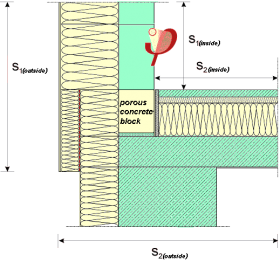
Example showing the thermal bridge free connection of the rising exterior masonry wall to the insulated floor slab (with indication of the reference dimension; as agreed, the exterior reference dimension is always used). The heat transfer coefficients were calculated for this detail depending on the base point block used here.
Besides, the remaining contributions are compensated to a certain extent by other connections where there are negative linear thermal transmittances. The [TbCrit] criterion is adequate for all structures which affect connections, edges, and individual interruptions in ruled surfaces. Recurrent interruptions in ruled surfaces must already be taken into account when giving the regular heat transfer coefficient Ureg (for example recurring shafts in a wood-stud or panel construction; the connection thermal bridge during the installation of a window is also appropriately included in the regular window U-value, this has already been applied in the PHPP and makes for less work).
With the simplified criterion, planning and construction become significantly easier: for a particular category of connection details, it only has to be verified once in advance that the [TbCrit] criterion has been met. This can be done, for example, by calculating all the relevant details for building envelopes. Many system manufacturers have already followed this approach and have ensured that their products comply with this criterion. If the planner uses these details, the thermal bridge unit (therm) can simply be omitted during the planning of the Passive House – this saves a lot of work during calculations.
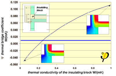
Dependence of the linear thermal transmittance (Ψ-value) on the thermal conductivity λ of the base point block. If this is smaller than 0.25 W/(mK), then Ψ ≤ 0.01 W/(mK) and consequently the detail will be thermal bridge free. This criterion is indicated by a horizontal blue line. However, one can also see that substantial thermal bridge losses can result with “normal blocks” (λ >0.8 W/(mK))
This example shows that “thermal bridge free design” can often be achieved with a few simple changes in the details and without incurring high costs. However, this must be recognised and taken into account during the planning. Making subsequent changes to the completed building, although technically possible, is unacceptably expensive. This is why significant thermal bridges still remain in this area in old buildings even after modernisation using Passive House components.
How to achieve a thermal bridge free design
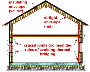
The following principle demonstrates this clearly: the insulation layers should be planned in such a way that one should be able to outline the minimum insulation thickness (20 cm for the Passive House) of the whole external envelope within the insulation layers using a pencil, without a break. The following figure illustrates this principle using a sectional drawing. The critical points can be easily identified in this way, e.g. the base point of the brick wall on the basement ceiling.
The purpose of “thermal bridge free design” is to substantially improve the details. A slightly more expensive substantial improvement of the connection details is preferable to recalculation in detail of less appropriate connections, which can be just as costly.
There have been positive experiences with numerous construction systems in which the principle of “thermal bridge free design” has already been applied. There are complete catalogues of thermal bridge free details now available for
- Solid constructions with solid bricks,
- Solid constructions with low-conductivity blocks (e.g. porous concrete blocks),
- Timber constructions (solid wood beams as well as lightweight beams),
- Constructions using formwork elements,
- Constructions using prefabricated lightweight concrete elements.
The Passive House Institute provides advice for manufacturers regarding the development of thermal bridge free constructions.
In the Protocol Volume 16 “Thermal bridge free design” that has often been mentioned here, numerous other details for building envelopes with thermal bridge free connections have been presented besides that shown here.
If a new building is not built in accordance with the principle of thermal bridge free design, there may be considerable heat losses as a result of the remaining thermal bridges. In various examples of building projects, there was an increase in the annual heating demand of up to 14 kWh/(m²a). For a construction project, careful planning with regard to thermal bridges can therefore be decisive for achieving the Passive House standard in the first place.